
In this tutorial you will learn how to use ADC and its functions of Nuvoton Microcontroller Board. There are different sensors available in electronics that provide Analog output, like the MQ gas sensors, ADXL335 Accelerometer sensor, etc. Thus, using analog to digital converters those sensors can be interfaced with a microcontroller unit. At the end of this tutorial, you will be able to build any project with a Nuvoton board and various types of Analog Sensor to read and encode them.
In this project we will be using Potentiometer as a variable Analog Value and Nuvoton MS51FB9AE Development Board.
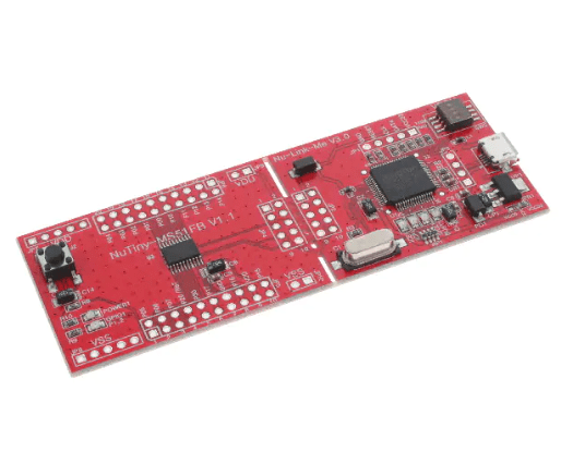
About Nuvoton MS51FB9AE Development Board
Nuvoton MS51FB9AE is an embedded flash type, 8-bit high performance 8051-based microcontroller based on 1T 8051-based CMOS, runs up to 24 MHz, features 16 K bytes flash, 1 K bytes SRAM, and 4 K bytes loader ROM for the ISP, also equipped with rich peripherals: 2 sets of UART; 1 set of I²C, and 1 set of SPI, 18 GPIO, 8 channels of 12-bit ADC, Watchdog Timer, Window Watchdog Timer and 6*16-bit PWM channel package is available in TSSOP20.
Hardware Requirements
For this project, we will use the below components-
1k resistor
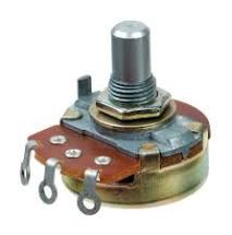
10K Potentiometer
Software Requirement
To write a code for Nuvoton MS51FB9AE module we would require Keil software.
Connections:
For LCD related connection:
RS - P04
EN - P03
D4 - P01
D3 - P00
D2 - P10
D1 - P11
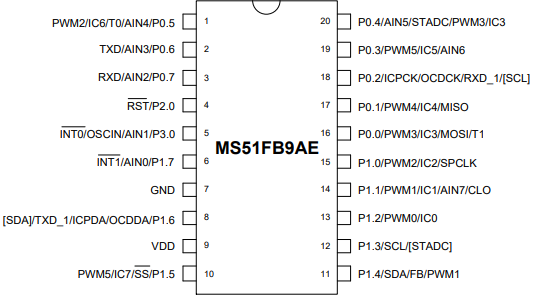
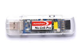
Connect the Nu-Link programmer to the board through USB from your PC to upload code.. The Input from IR Sensor is sensed by the analog input 0 (AN0), Pin P1.7 which is Analog input channel 0 is used to interface IR sensor.
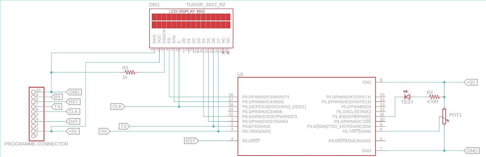
As we can see in the schematic, the port P0 is used for the LCD related connection. On the extreme left, the programming interface connection is shown. The potentiometer acts as a voltage divider and that is sensed by the analog input 0 (AN0).
Code
As we are using Keil for this project you would be requiring a powerful LCD and MS51FB9AE library for proper debugging the Output from our IR sensor, Download 16x2 LCD Library for Nuvoton MS51FB9AE from here and download MS51 library here.
After downloading just add lcd.c and lcd.h and ms51.h files in your main Keil MS51FB9AE project.
#include "ms51.h"
#include "SFR_Macro.h"
#include "Function_define.h"
#include "Common.h"
#include "Delay.h"
#include "lcd.h"
#define bit_to_voltage_ratio 0.001220703125 // 5.0V divided by 4096 For 12-Bit ADC
void setup (void);
unsigned int ADC_read(void);
float voltage;
char str_voltage[20];
void main(void){
int adc_data;
setup();
lcd_com (0x01);
while(1){
lcd_com (0x01);
lcd_com (0x80);
lcd_puts("ADC Data: ");
adc_data = ADC_read();
lcd_print_number(adc_data);
voltage = adc_data * bit_to_voltage_ratio;
sprintf( str_voltage, "Volt: %0.2fV", voltage);
lcd_com(0xC0);
lcd_puts(str_voltage);
Timer0_Delay1ms(500);
}
}
void setup (void){
Set_All_GPIO_Quasi_Mode;
lcd_init();
Enable_ADC_AIN0;
lcd_com (0x80);
LCD_ScrollMessage("Welcome to CampusComponent");
lcd_com (0x80);
lcd_puts("IR sensor Interfacing");
lcd_com (0xC0);
lcd_puts ("With MS51FB9AE mcu");
Timer3_Delay100ms(5);
}
unsigned int ADC_read(void){
register unsigned int adc_value = 0x0000;
clr_ADCF;
set_ADCS;
while(ADCF == 0);
adc_value = ADCRH;
adc_value <<= 4;
adc_value |= ADCRL;
return adc_value;
}
Output
After successfully uploading of the code, start the Input supply and vary the potentiometer connected to the ADC pin, the Pot value given to the ADC pin will show some change and we can notice the ADC value and Analog voltage displayed on the LCD. At lowest ADC value will be 0 and at highest pot value ADC value will show 4096 i.e. 12 bit ADC. By further calibration you can achieve more accurate values and you work with it as per your requirements.
Conclusion
Using the above process you can make Nuvoton microcontroller and any Analog Sensor work as you need. There are many high end industrial projects you can build and explore using Nuvoton development Board. There are different modules from Nuvoton which come with more add-on functionality and hardware peripherals which are available at Campus Component.
The Nuvoton module can be used in varied applications such as Thermostat, Bluetooth Speaker, Infrared Sensing, Battery charger, Small IoT appliances. In terms of industrial projects we can use Nuvoton Module to build Rail safety devices, Infrared Astronomy, optical power meters and Large scale IoT projects.
If you are looking for electronic components and different microcontrollers from Nuvoton, reach out to the best electronic components online store- Campus Component today!

