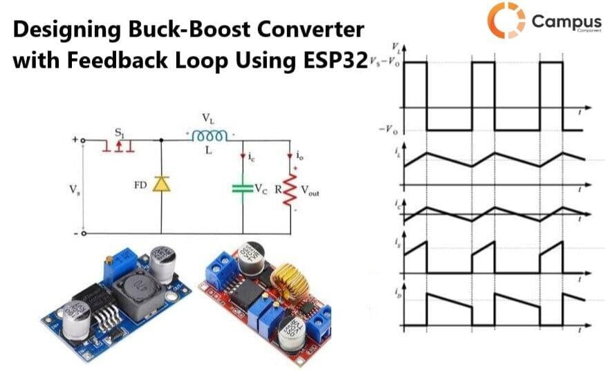
A buck-boost converter is a switch-mode DC-DC converter that provides an output voltage greater than or less than the input voltage. The process of reducing the voltage then its input voltage is called Buck and where the output voltage is increased in terms of its input voltage then it is called as Boost. The arrangement of a buck-boost converter circuit is similar to that of the buck converter and boost converter circuits; it’s a combination of both buck and boost circuit.
This blog post will guide you through the process of building a Buck-Boost Converter, also we will implement an Error correction feedback loop using ESP32.
Objectives
To build a controller to switch between the Buck-Boost operations
Control the output voltage by varying the Duty cycle by providing required PWM value from microcontroller.
Fundamentals of Buck-Boost Converter
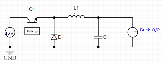
Buck Converter
Buck converter is a dc-to-dc converter designed to perform the step down conversion to perform the step down conversion of applied dc input.
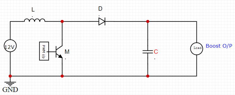
Boost Converter
Boost converter performs the step up conversion of voltage from its input to load.
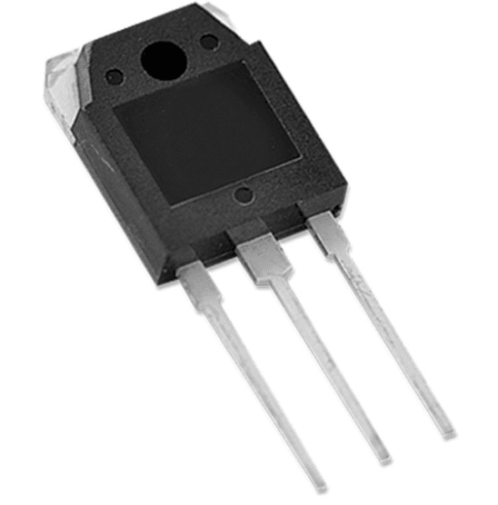
So as per the working of Buck and Boost Converter the Step down and Step-up of the voltage at the output depends on the Duty Cycle(square wave) applied to the switch (i.e. mosfet ) by varying PWM value.
Formula for Voltage Calculation
For Buck Converter
Vo = Vin * Duty Cycle
For Boost Converter
Vo =11-Duty Cycle*Vin
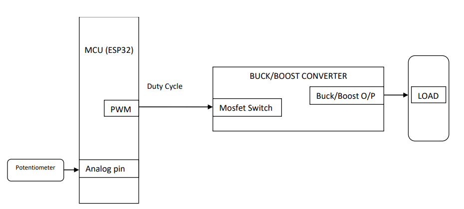
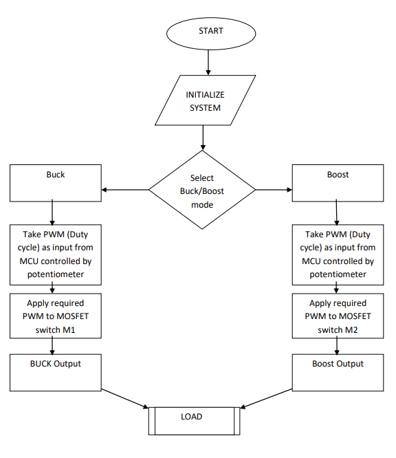
As shown in the block diagram, we will integrate ESP32’s PWM to change the Duty cycle which is applied to the switch(mosfet) to control the switching frequency.
This PWM pin will take the input from the Potentiometer which is connected to one of the Analog pins of ESP32 Microcontroller, this varied analog value will be fed to the PWM pin through the code, and this value will be mapped according to the required PWM.
Hardware Requirements
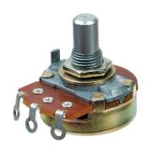
2. Potentiometer
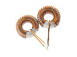
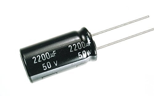
Inductors and Capacitors
System Flowchart
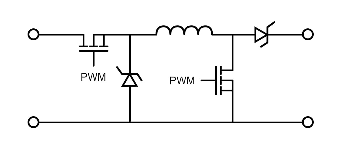
Designing the Buck-Boost Converter With Feedback Circuit
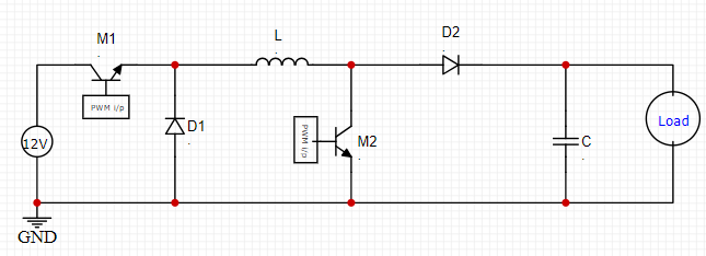
In buck boost combination circuit when S1 is shorted, the circuit works as a boost converter providing the output voltage of 1/(1-D)*Vin and when S2 is shorted, the circuit works as a buck converter with an output voltage of D*Vin.
In buck boost combination circuit when S1 is shorted, the circuit works as a boost converter providing the output voltage of 1/(1-D)*Vin and when S2 is shorted, the circuit works as a buck converter with an output voltage of D*Vin.
The Buck-Boost Converter Circuit is Controlled by PWM Signals
By adding feedback from the output and input terminals and giving it back to ESP32, we can make an automatic buck-boost converter circuit that automatically adjusts the output voltage which keeps it constant throughout the operation. In addition to the previous circuit, we have to use a voltage divider for input and output voltage sensing and to provide this data to the analog input pins of the ESP32.
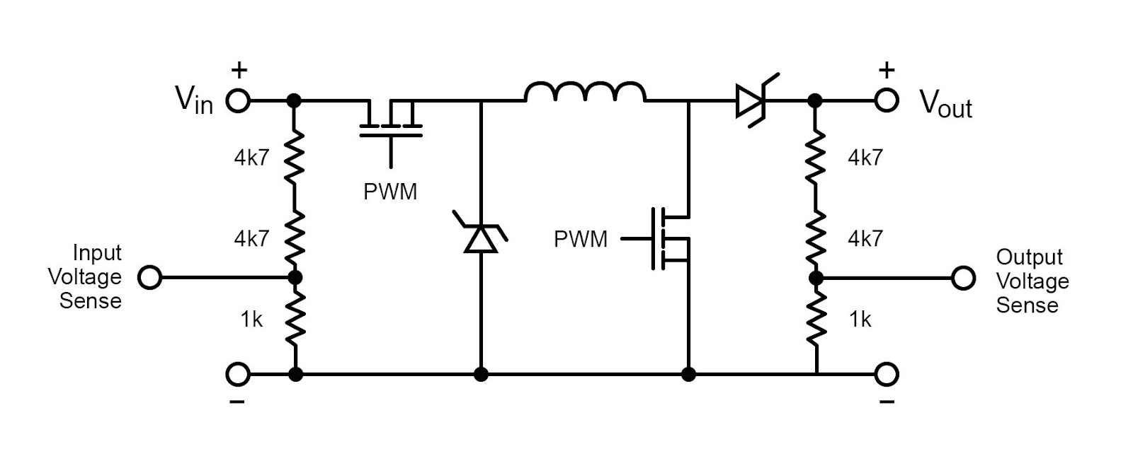
The circuit after adding feedback from the output/input terminals and a voltage divider for input/output voltage sensing.
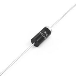
Input voltage data goes to the ESP32 analog pin and the output voltage goes to another analog pin . Also, note that we use Schottky diodes to minimize diode losses; 1N5817 Schottky diodes are perfect for such applications.
Thus we have made an automatic buck-boost converter that automatically stabilizes the output voltage with the help of feedback-based input and output voltage sensing. Using ESP32.
By adding feedback from the output and input terminals and giving it back to ESP32, we can make an automatic buck-boost converter circuit that automatically adjusts the output voltage which keeps it constant throughout the operation. In addition to the previous circuit, we have to use a voltage divider for input and output voltage sensing and to provide this data to the analog input pins of the ESP32.
The circuit after adding feedback from the output/input terminals and a voltage divider for input/output voltage sensing.
Input voltage data goes to the ESP32 analog pin and the output voltage goes to another analog pin . Also, note that we use Schottky diodes to minimize diode losses; 1N5817 Schottky diodes are perfect for such applications.
Thus we have made an automatic buck-boost converter that automatically stabilizes the output voltage with the help of feedback-based input and output voltage sensing. Using ESP32.
Upload the Following Code After Building the Circuit in ESP32
Code Implementation
#define vin_pin A1
#define output_voltage_sense A2
#define input_voltage_sense A0
#define boost_pin 5
#define buck_pin 6
int raw_vin = 0, raw_vout = 0, raw_iout = 0;
float Vout_max = 13.0, Iout_max = 1.0, Vout_min = 11.1, Iout_min = 0.1, Vin_thresold = 10.5;
float Iout_sense;
float Vout_sense;
float Vin_sense;
uint8_t duty_cycle = 25;
String mode = "";
bool startup = true;
unsigned int count = 0;
void setup() {
Serial.begin(115200);
TCCR0B = TCCR0B & 0b11111000 | 0x01;
analogWrite(buck_pin, 255);
analogWrite(boost_pin, 0);
}
void loop() {
if (Serial.available()) {
String data = Serial.readString();
Vout_max = data.toInt();
Vout_max = Vout_max / 10;
Serial.print("Vout_max= ");
Serial.println(Vout_max);
}
for (int i = 0; i < 10; i++) {
raw_iout += analogRead(input_voltage_sense) - 513;
raw_vin += analogRead(vin_pin);
raw_vout += analogRead(output_voltage_sense);
}
raw_iout = raw_iout / 10;
raw_vout = raw_vout / 10;
raw_vin = raw_vin / 10;
Iout_sense = float(raw_iout) * 0.0586;
Vout_sense = float(raw_vout) * 0.046;
Vin_sense = float(raw_vin) * 0.046;
if (count > 100) {
Serial.print("Vin= "); Serial.println(Vin_sense);
Serial.print("Vout= "); Serial.println(Vout_sense);
Serial.print("Iout= "); Serial.println(Iout_sense);
Serial.print("Duty cycle=" ");" Serial.println(duty_cycle);
Serial.print("Converter MODE : "); Serial.println(mode);
count = 0;
}
if (!startup) {
regulate(Iout_sense, Vin_sense, Vout_sense);
auto_cutoff(Iout_sense, Vin_sense, Vout_sense);
} else {
soft_start();
}
delay(600);
count++;
}
void regulate(float Iout, float Vin, float Vout) {
if (Vout_max < Vin) {
mode = "Buck mode";
analogWrite(boost_pin, 0);
if ((Iout < Iout_max && Iout > Iout_min) && (Vout < Vout_max)) {
if (duty_cycle < 250) {
duty_cycle += 2;
}
analogWrite(buck_pin, 255 - duty_cycle);
} else if ((Iout > Iout_max) || (Vout > Vout_max)) {
if (duty_cycle > 2) {
duty_cycle -= 2;
}
analogWrite(buck_pin, 255 - duty_cycle);
}
} else if (Vout_max > Vin) {
mode = "Boost mode";
analogWrite(buck_pin, 0);
if ((Iout < Iout_max) && (Vout < Vout_max)) {
if (duty_cycle < 220) {
duty_cycle += 2;
}
analogWrite(boost_pin, duty_cycle);
} else if ((Iout > Iout_max) || (Vout > Vout_max)) {
if (duty_cycle > 4) {
duty_cycle -= 2;
}
analogWrite(boost_pin, duty_cycle);
}
}
}
void auto_cutoff(float Iout, float Vin, float Vout) {
if ((Vout >= Vout_max && Iout < Iout_min) || (Vin < Vin_thresold)) {
analogWrite(boost_pin, 0);
analogWrite(buck_pin, 255);
Serial.println("Charging Completed.");
delay(64000);
}
}
void soft_start() {
if (Vout_sense <= Vout_min) {
regulate(Iout_sense, Vin_sense, Vout_sense);
Serial.print("Vin= "); Serial.println(Vin_sense);
Serial.print("Vout= "); Serial.println(Vout_sense);
Serial.print("Iout= "); Serial.println(Iout_sense);
Serial.print("Duty cycle=" ");" Serial.println(duty_cycle);
Serial.print("Converter MODE : "); Serial.println(mode);
Serial.println("Soft Start Activated");
delay(64000);
} else {
startup = false;
}
}
Conclusion
Thus, we Designed a Buck-Boost Converter with feedback loop using ESP32. There are various applications of this Buck-Boost converter such as It is used in the self regulating power supplies, It is used in the Battery power systems, Adaptive control applications, Power amplifier applications.
If you are building a Buck-Boost converter and looking for electronic components such as ESP32 and other microcontroller by trusted brands such as Espressif, and other components reach out electronics components suppliers in India- Campus Component today!

