What is a voltage divider?
Voltage divider is an electrical circuit which is used to convert high voltage to low voltage using a couple of resistors. It plays a crucial role in microcontrollers, relays, diodes by supplying required voltage from the higher voltage.
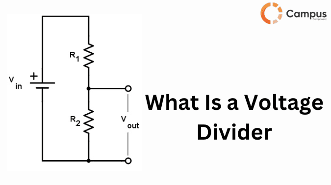
The voltage divider consists of two resistors connected in series. Input power supply is connected across both the resistors and output is calculated across one resistor. The ratio of the resistor decides the output voltage. For example, in microcontroller based applications, a voltage divider is used to step down higher voltages (5v or 12v ) to lower voltage (3.3v or 5v) .

Types of Voltage Dividers
Depending on the components used, voltage divider is divided in different types :
1. Resistive Voltage Divider
It is one of the most widely used voltage divider which consists of two or more resistors connected in the series. It works on the formula:
Vo = Vin x ( R2 / R1 + R2 )
This divider is suitable for low power applications and not for high current loads due to power dissipation. Hence this type is used in microcontroller ADC circuits, signal level shifting etc.
2. Capacitive Voltage Divider
This voltage divider uses capacitors instead of resistors to divide the voltage. Capacitive voltage divider is mainly used in AC circuits and high-frequency applications like filtering, impedance matching in RF circuits. It works on the formula:
Vo = Vin x (C1 / C1 + C2 )
This type of divider is more energy efficient in alternating current applications as capacitors do not dissipate power as heat.
3. Inductive Voltage Divider
Inductive voltage divider depends on inductors or transformers to divide the voltage. It is used in radio frequency applications, power distribution and electrical isolation. It works on the formula :
Vo = Vin x (N2 / N1)
Here N1 and N2 are the number of turns in the primary and secondary windings. This type of voltage divider is used for high power applications.
4. Zener Voltage Divider
This consists of a Zener diode and resistor. They maintain the output voltage regardless of the variations in input voltage. Once the voltage reaches the breakdown voltage, Zener diode stabilizes it ensuring a consistent output voltage.
5. Potentiometer Voltage Divider
Potentiometer is a variable resistor which makes it unique for the applications which require manual tuning of voltage levels such as audio controls, sensor calibration. Potentiometer based voltage divider allows for an adjustable output voltage.
Functions of Voltage Divider
1.Stepping down a higher voltage to a lower voltage is one of the primary functions of a voltage divider.
2. A precise reference voltage ensures accurate signal measurement and processing in analog to digital converters. That’s why voltage dividers are used to generate a stable reference voltage.
3. Signals that are produced by sensors and transducers need to be scaled, a voltage divider adjusts the signal to a suitable range by ensuring compatibility with the receiving circuit.
4.Voltage divider are used for biasing transistors and other devices to ensure stable performance and prevent distortion in signal amplification.
5.Voltage dividers are used to monitor output voltage levels in power supply units to ensure efficient power management.
6. Voltage divider shows an important role in impedance matching between different circuits.
How does a voltage divider work?
Voltage divider works on the principle of Ohm’s law and voltage division principle. The most common is a resistive type voltage divider in which two resistors are connected in series across input voltage. It works on the formula:
Vo = Vin x (R2 / R2 + R1)
Firstly input voltage is distributed across R1 and R2 based on their resistive values. If the resistance is large, the large will be the voltage drop across it.
Following ohm’s law, small current flows through both resistors. The current through both the resistors is the same as the resistors are connected in series.
At the connection between R1 and R2, the output voltage appears which is determined by the resistance ratio. The appeared voltage is less than the input voltage which is then used for various applications.
Creating Voltage Divider With Resistors
Below are the steps to create voltage divider with resistors :
1.First know the voltage you need to step down and the required output voltage.
2.After that choose the resistor values that maintain a stable voltage ratio while minimizing power loss.
3.Do the proper connection :
Connect R1 between Vin and the output node.
Connect R2 between the output node and ground.
Measure Vo across R2.
Application and Uses of Voltage Dividers
1. Voltage divider are used with microcontrollers as they operate at different voltage levels.
2. They are also used in Analog to Digital converters.
3. In solar power systems, electric vehicles and battery management systems voltage divider is used to monitor the battery levels.
4. To generate the stable reference voltage, voltage divider is used in electronic circuits like op-amps, comparators and regulators.
5. To sense the voltage drop across the loads, voltage dividers are used in industrial automation and motor control applications.
Voltage Divider In Integrated Circuits
Voltage dividers play important role in integrated circuits and they help to :
Convert high voltage to lower levels which is suitable for IC operation.
Generate reference voltage for analog and digital circuits.
Interface different voltage logic levels.
Bias transistors and operational amplifiers within IC.
Frequently Asked Questions
1. What is the basic formula for a voltage divider?
The basic formula for voltage divider is :
Vo = Vin x ( R2 / R1 + R2 )
Where Vo is output voltage, Vin is input voltage and R1 and R2 are resistor values.
2. Can a voltage divider be used for high power application?
No, a voltage divider is not suitable for high-power applications due to excessive power dissipation and poor efficiency; voltage regulators or transformers are preferred instead.
3. Why is a voltage divider not ideal for powering active components?
A voltage divider is not ideal for powering active components because it cannot provide a stable output under varying loads, leading to voltage fluctuations and inefficiency.
4. How does load resistance affect the accuracy of a voltage divider?
Load resistance affects the accuracy of a voltage divider by creating a parallel resistance with the lower resistor (R₂), altering the voltage ratio and causing Vout to drop below the expected value.
5. Can a voltage divider be used to step down AC voltage?
Yes, a voltage divider can step down AC voltage using resistors or a combination of resistors and capacitors, but for efficient AC voltage regulation, transformers are preferred.

