![]()
In industrial applications like logistics and inventory management tracking applications are used on a large level. GPS Tracking is also used in cab services, vehicle monitoring, human tracking, asset management, and public transport surveillance. However, traditional vehicle tracking systems that rely on GSM technology often encounter challenges in areas with poor signal coverage, limiting their effectiveness. The introduction of ESP8266 with a LoRa-based GPS tracker is the solution to this problem, where you can track your asset from any remote location in the world. In this project article we will build a LoRa Based Low Power GPS Tracker with ESP8266 and also look at how you can integrate the same with Nuvoton N032LE3AE module.
Components Required
Neo 6M GPS Module
LM2596 Step-down Converter.
LoRa Gateway
LoRa GPS Tracker Working
In our previous blogs we have discussed how LoRa modules work and how they are ideal for low power wireless applications. To establish a connection between any LoRa module and The Things Network, a primary prerequisite is a LoRa gateway. Learn more about LoRa in IOT.
The project has simple working: the ESP8266 serves as the primary controller. It gets/collects information from the Neo-6M GPS Module, transforming Latitude and Longitude data into a LoRa Packet. This packet is then transmitted to the HPD13A LoRa module, establishing a connection with a nearby gateway. Once linked to a LoRa gateway, the packet is forwarded to The Things Network, where the raw data can be viewed on the Things Network Dashboard. To enhance functionality, we've implemented a webhook integration, allowing the position data to be seamlessly sent to Ubidots. Leveraging this information on Ubidots enables us to create a user-friendly map interface for visualizing our location data.
ESP8266 integrated with LoRa GPS Tracker Circuit Diagram is shown below

The connections for the Nodemcu LoRa GPS Tracker with ESP8266 are shown above in the circuit diagram. We use an LM2596 Step-Down Converter to lower the input voltage, ranging from 9-12V from a Li-Po Battery, to 4.2V. This lower voltage powers both the ESP8266 and the Neo-6M GPS Module. The LoRa module receives power from the ESP8266 at 3.3V and communicates through the SPI Pins. When uploading the code to the ESP8266, ensure the Neo-6M is disconnected since it is connected to the hardware serial pins of the ESP8266 during this process.
Setting Up End Node on The Things Network
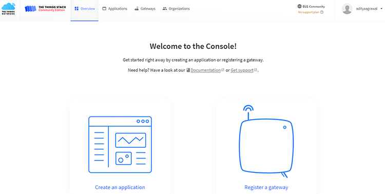
To begin, sign up on The Things Network by creating either an individual or a student account, both are free. When choosing the LoRa Cluster, opt for the EU Cluster if you're not situated in North America or Australia. After successfully creating your account and completing the email verification, you'll gain access to the TTN Console, which is as shown below.
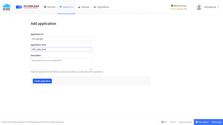
Click -> create application -> Enter unique application ID -> application name -> create.
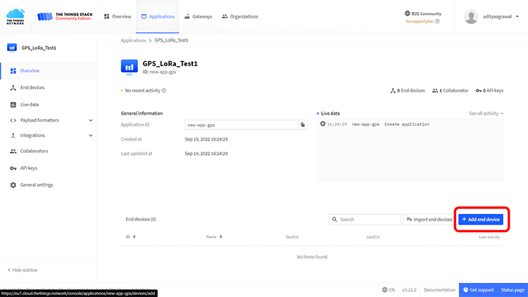
When your application gets created go to add an end device.
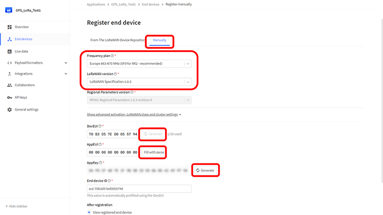
Click -> Manually -> Enter parameters -> generate the DevUI, AppEUI, AppKey, -> complete the end device creation.
Switch to “Payload Formatters” once your device gets created
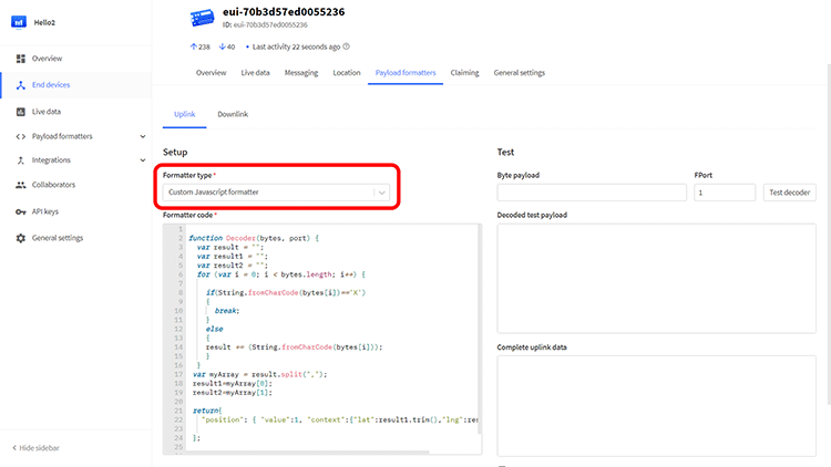
Choose "Custom JavaScript formatter" under the Formatters Type option, and insert the provided code below:.
function Decoder(bytes, port) {
var result = "";
var result1 = "";
var result2 = "";
for (var i = 0; i < bytes.length; i++) {
if(String.fromCharCode(bytes[i])=='X') {
break;
}
else {
result += (String.fromCharCode(bytes[i]));
}
}
var myArray = result.split(",");
result1=myArray[0];
result2=myArray[1];
return {
"position": { "value":1, "context":{"lat":result1.trim(),"lng":result2.trim()}}
};
}
Now that we've set up our end device on the Things Network, let's move on to programming the ESP8266. Open the device overview and copy the DevUI, AppEUI, and AppKey. Make sure to set the LSB order for DevUI and AppEUI, and the MSB order for AppKey.
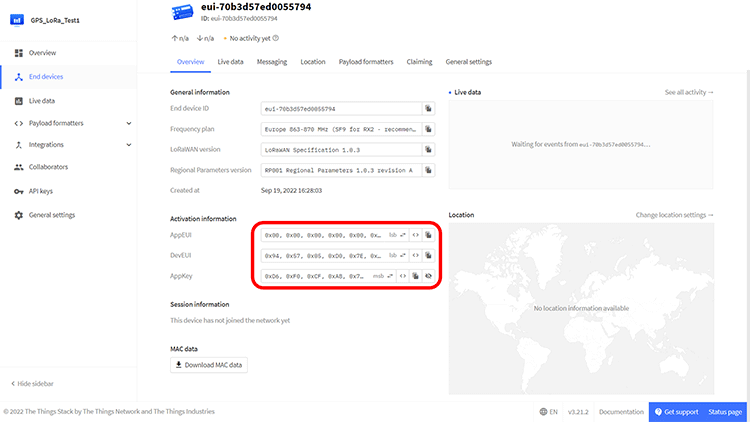
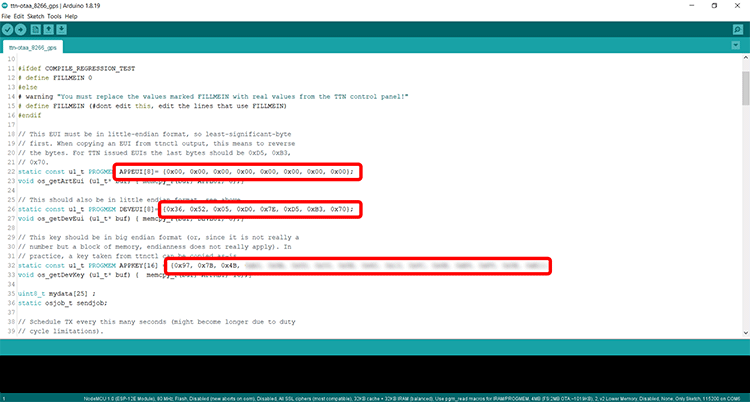
Open the ESP8266 code (given at the end of the blog) in Arduino IDE and paste those IDs in their respective fields in the code.
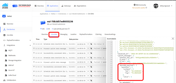
After uploading the ESP8266 code, your device will begin transmitting LoRa data to The Things Network, and you can track this activity in the "Live Data" tab.
Ubidots Connection Setup For Data Visualization
Now that our data is reaching TTN, let's integrate a Ubidots Dashboard. Since our data includes Latitude and Longitude Coordinates, we can use Ubidots' Maps Widget. To begin, create a Ubidots STEM account and open your dashboard.
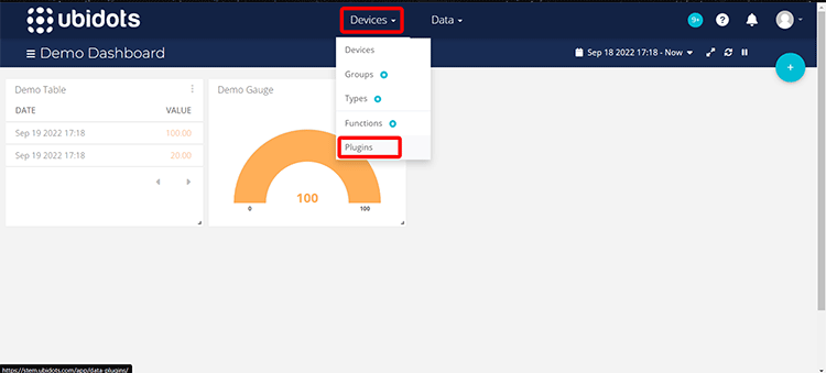
Select -> Devices Menu -> Select Plugins.
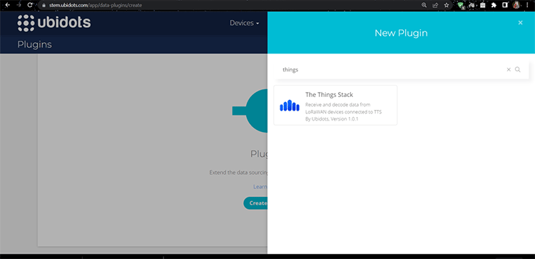
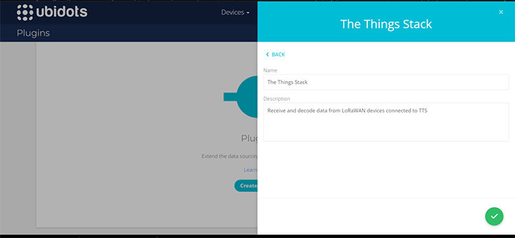
Search and select -> “The Things Stack” option
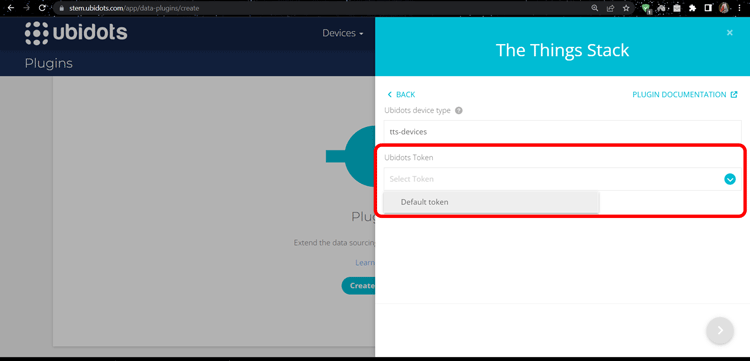
Leave the rest of settings to default and select the Ubidots Token as Default Token
Add the name and description of the plug-in -> Click on Create.
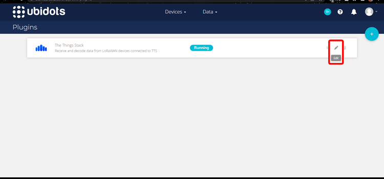
Your plugin is now active next click on the "Edit Plugin" option.
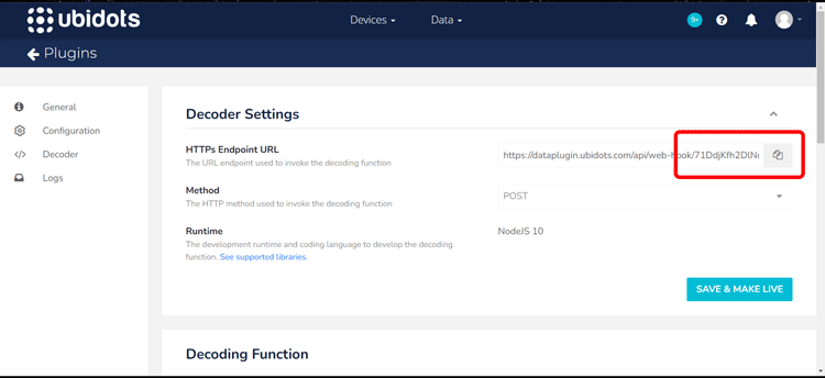
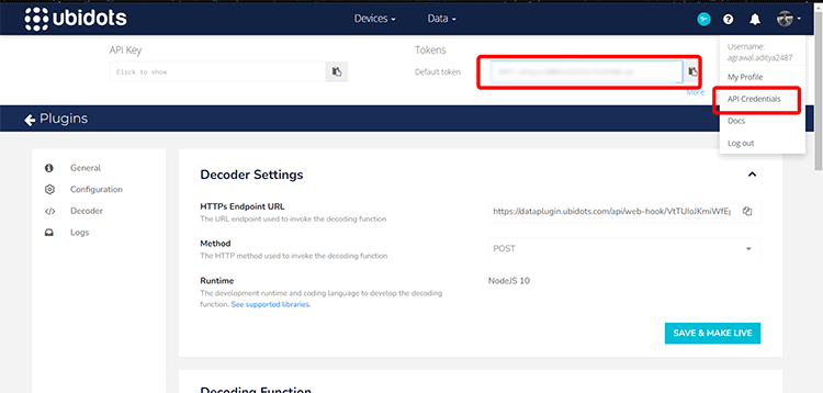
In the decoder settings, find the HTTPs Endpoint URL. This URL is where we'll set up the TTN Server to send data packets. Copy the Plugin ID, which is the part of the URL that comes after the /api/webhook/ section.
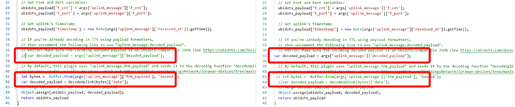
After completing the previous steps, scroll down to the Decoder Function panel and uncomment the following line of code.
//var decoded_payload = args['uplink_message']['decoded_payload'];
//Also, comment on the following two lines.
//let bytes = Buffer.from(args['uplink_message']['frm_payload'], 'base64');
//var decoded_payload = decodeUplink(bytes)['data'];
Select the "Save & Make Live" button. Our integration is now set up on the Ubidots side. Before going to TTN, navigate to the API credentials option in your profile menu and copy the default token this will be useful later on.
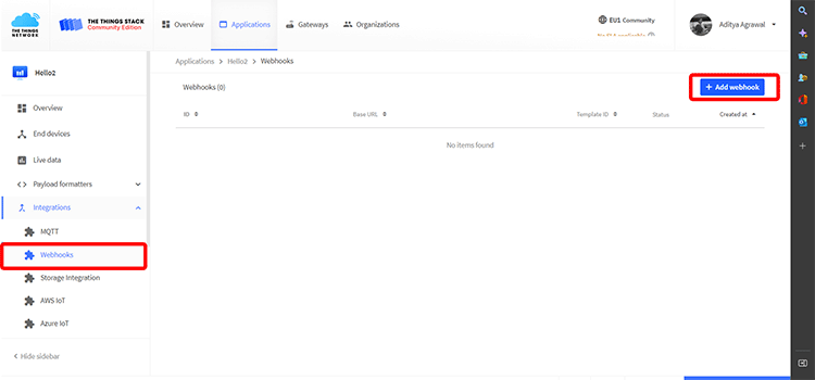
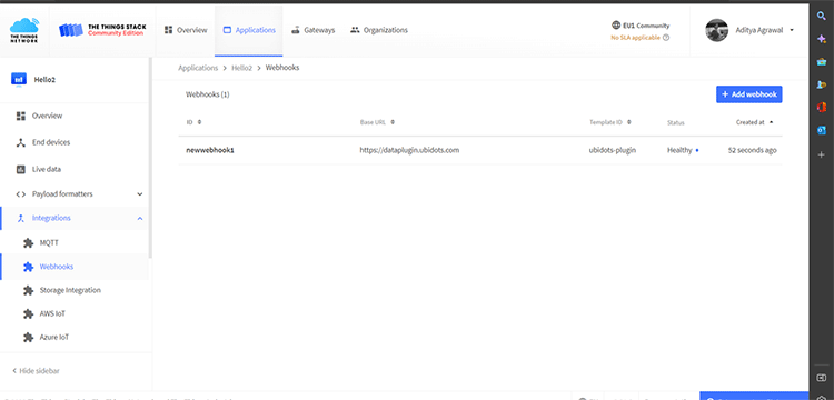
Open TTN Application -> Integrations panel -> Webhooks -> Add Webhook button.
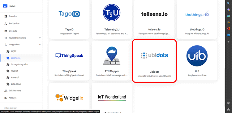
Select the Ubidots plugin from the given options.
Further enter your Plugin ID and your Ubidots Token.
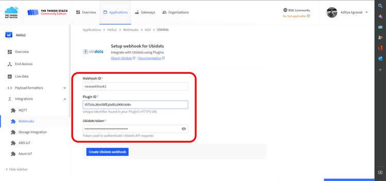
And that’s it your integration webhook is successfully created
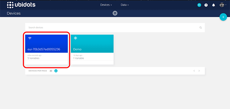
After completing this integration, our LoRa device will transmit data to our TTN Server. Open your Ubidots dashboard, and on the Devices page, your device will be seen here.
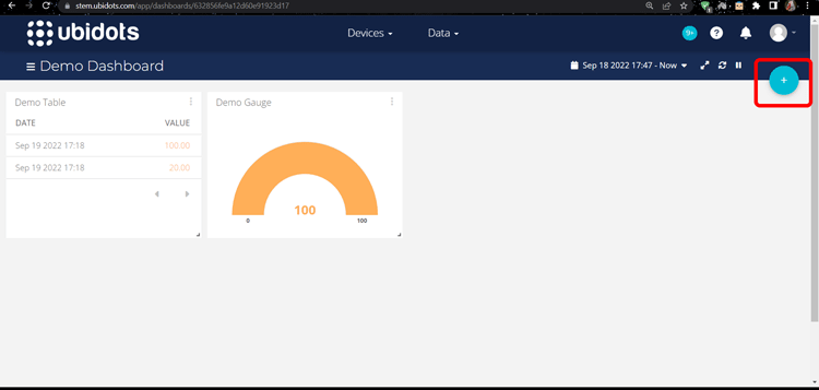
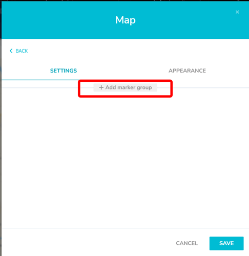
Final step is to add a Map Widget to your dashboard. Select -> Data Tab -> Dashboards -> Create Widget Button.
Add new Widget -> Map
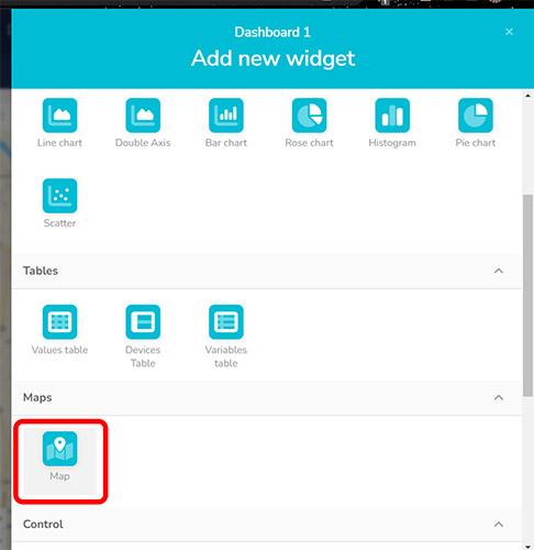
Select Add Marker Group.
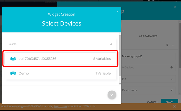
Select your LoRa Device.
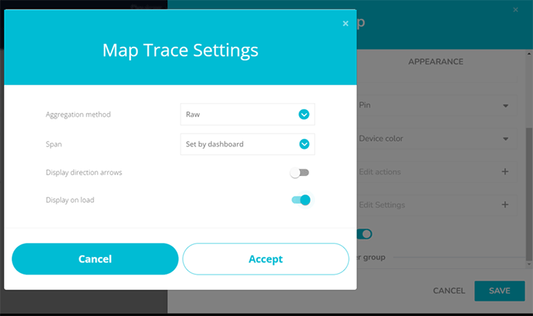
Customize the Map Trace settings as per your preferences and then click on the Save button.Top of Form
That's all! Now, all the location and tracking data from the LoRa device will appear on the map widget as location markers. You can also edit your dashboard by adding other widgets like tables to display appropriate coordinate values.
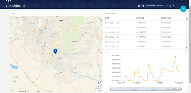
Working Of Our LoRA Based Low power GPS Tracker with ESP8266
The image below depicts the physical setup and shows how the latitude and longitude values are updated on Ubidots. The range of our LoRa GPS tracker relies on the availability of LoRa Gateways available in the area. As long as a gateway is within reach of your LoRa module, you'll be able to successfully send data to Ubidots.
ESP8266 Code
#include <lmic.h>
#include <hal/hal.h>
#include <SPI.h>
#include <TinyGPSPlus.h>
TinyGPSPlus gps; String ProcData="Hello,World";
#ifdef COMPILE_REGRESSION_TEST
# define FILLMEIN 0
#else
# warning "You must replace the values marked FILLMEIN with real values from the TTN control panel!"
# define FILLMEIN (#dont edit this, edit the lines that use FILLMEIN)
#endif
// This EUI must be in little-endian format, so least-significant-byte
// first. When copying an EUI from ttnctl output, this means to reverse // the bytes. For TTN issued EUIs the last bytes should be 0xD5, 0xB3,
// 0x70. static const u1_t PROGMEM APPEUI[8]= {0x00, 0x00, 0x00, 0x00, 0x00, 0x00, 0x00, 0x00}; void os_getArtEui (u1_t* buf) { memcpy_P(buf, APPEUI, 8);}
// This should also be in little endian format, see above.
static const u1_t PROGMEM DEVEUI[8]= {0x36, 0x52, 0x05, 0xD0, 0x7E, 0xD5, 0xB3, 0x70};
void os_getDevEui (u1_t* buf) { memcpy_P(buf, DEVEUI, 8);}
// This key should be in big endian format (or, since it is not really a
// number but a block of memory, endianness does not really apply). In
// practice, a key taken from ttnctl can be copied as-is.
static const u1_t PROGMEM APPKEY[16] = {0x97, 0x7B, 0x4B, 0xA3, 0x9A, 0x8D, 0x33, 0x5E, 0x42, 0x13, 0x9C, 0x6B, 0xE9, 0xF9, 0x5E, 0xE1};
void os_getDevKey (u1_t* buf) { memcpy_P(buf, APPKEY, 16);}
uint8_t mydata[25] ;
static osjob_t sendjob;
// Schedule TX every this many seconds (might become longer due to duty
// cycle limitations). const unsigned TX_INTERVAL = 2;
// Pin mapping
const lmic_pinmap lmic_pins = {
.nss = 15,
.rxtx = LMIC_UNUSED_PIN,
.rst = 16,
.dio = {5, 4, LMIC_UNUSED_PIN},
};
void printHex2(unsigned v) {
v &= 0xff;
if (v < 16)
Serial1.print('0');
Serial1.print(v, HEX);
}
void onEvent (ev_t ev) {
Serial1.print(os_getTime());
Serial1.print(": ");
switch(ev) {
case EV_SCAN_TIMEOUT: Serial1.println(F("EV_SCAN_TIMEOUT"));
break;
case EV_BEACON_FOUND: Serial1.println(F("EV_BEACON_FOUND"));
break;
case EV_BEACON_MISSED: Serial1.println(F("EV_BEACON_MISSED"));
break;
case EV_BEACON_TRACKED: Serial1.println(F("EV_BEACON_TRACKED"));
break;
case EV_JOINING: Serial1.println(F("EV_JOINING"));
break;
case EV_JOINED: Serial1.println(F("EV_JOINED")); {
u4_t netid = 0; devaddr_t devaddr = 0;
u1_t nwkKey[16];
u1_t artKey[16];
LMIC_getSessionKeys(&netid, &devaddr, nwkKey, artKey);
Serial1.print("netid: ");
Serial1.println(netid, DEC);
Serial1.print("devaddr: ");
Serial1.println(devaddr, HEX);
Serial1.print("AppSKey: ");
for (size_t i="0;" i<sizeof(artKey); ++i) {
if (i != 0) Serial1.print("-");
printHex2(artKey[i]);
}
Serial1.println("");
Serial1.print("NwkSKey: ");
for (size_t i="0;" i<sizeof(nwkKey); ++i) {
if (i != 0) Serial1.print("-");
printHex2(nwkKey[i]);
}
Serial1.println(); }
// Disable link check validation (automatically enabled
// during join, but because slow data rates change max TX
// size, we don't use it in this example. LMIC_setLinkCheckMode(0); break;
/* || This event is defined but not used in the code. No || point in wasting codespace on it. || || case EV_RFU1: || Serial1.println(F("EV_RFU1")); || break; */
case EV_JOIN_FAILED: Serial1.println(F("EV_JOIN_FAILED"));
break;
case EV_REJOIN_FAILED: Serial1.println(F("EV_REJOIN_FAILED"));
break;
case EV_TXCOMPLETE: Serial1.println(F("EV_TXCOMPLETE (includes waiting for RX windows)"));
if (LMIC.txrxFlags & TXRX_ACK) Serial1.println(F("Received ack"));
if (LMIC.dataLen) {
Serial1.print(F("Received "));
Serial1.print(LMIC.dataLen); Serial1.println(F(" bytes of payload"));
}
// Schedule next transmission
os_setTimedCallback(&sendjob, os_getTime()+sec2osticks(TX_INTERVAL), do_send);
break;
case EV_LOST_TSYNC: Serial1.println(F("EV_LOST_TSYNC"));
break;
case EV_RESET: Serial1.println(F("EV_RESET"));
break;
case EV_RXCOMPLETE: // data received in ping slot Serial1.println(F("EV_RXCOMPLETE"));
break;
case EV_LINK_DEAD: Serial1.println(F("EV_LINK_DEAD"));
break;
case EV_LINK_ALIVE: Serial1.println(F("EV_LINK_ALIVE")); break;
/* || This event is defined but not used in the code. No || point in wasting codespace on it. || || case EV_SCAN_FOUND: || Serial1.println(F("EV_SCAN_FOUND")); || break; */
case EV_TXSTART: Serial1.println(F("EV_TXSTART"));
break;
case EV_TXCANCELED: Serial1.println(F("EV_TXCANCELED"));
break;
case EV_RXSTART: /* do not print anything -- it wrecks timing */
break;
case EV_JOIN_TXCOMPLETE: Serial1.println(F("EV_JOIN_TXCOMPLETE: no JoinAccept"));
break;
default: Serial1.print(F("Unknown event: "));
Serial1.println((unsigned) ev);
break;
}
}
void do_send(osjob_t* j){
// Check if there is not a current TX/RX job running
if (LMIC.opmode & OP_TXRXPEND) {
Serial1.println(F("OP_TXRXPEND, not sending"));
}
else {
// Prepare upstream data transmission at the next possible
time. unsigned long start = millis();
do {
while (Serial.available())
gps.encode(Serial.read());
}
while (millis() - start < 1000);
float flat="gps.location.lat();
float flon="gps.location.ln"g();
char charLat[20];
char charLong[20];
Serial1.print("Cords: ");
Serial1.print(flat); Serial1.print(" , ");
Serial1.println(flon);
dtostrf(flat, 10, 7, charLat);
dtostrf(flon, 10, 7, charLong);
sprintf((char *)mydata, "%s,%sX", charLat,charLong);
LMIC_setTxData2(1, mydata,25, 0);
Serial1.println(F("Packet queued"));
//int x="ProcData.len"gth();
//ProcData.toCharArray((char *)mydata,sizeof(mydata));
}
// Next TX is scheduled after TX_COMPLETE event.
}
void setup() {
Serial1.begin(9600);
Serial1.println(F("Starting"));
Serial.begin(9600);
// LMIC init os_init();
// Reset the MAC state. Session and pending data transfers will be discarded. LMIC_reset(); LMIC_setClockError(MAX_CLOCK_ERROR * 1 / 100);
// Start job (sending automatically starts OTAA too) do_send(&sendjob);}
void loop() {
os_runloop_once();
}
Conclusion
Thus we have implemented a LoRa based low power GPS tracker with ESP8266, you can track any of your device location using this setup in your project. The same process as above will be followed if you are building a GPS tracker using Nuvoton N032LE3AE. The LoRa-based Low Power GPS Tracker with ESP8266 gives multiple options and ways to enhance your IoT devices. Offering extended battery life, precise location tracking, real-time monitoring, cost-effectiveness, and versatile connectivity.
If you are looking for LoRa Module and GPS module from brands such as Smatech and Hoperf or microcontrollers from brands like Nuvoton and Espressif reach out to Campus Component an electronic components distributor today!

