What is GSM?
GSM stands for the global system of mobile communication. Generally, It is used in all mobiles used around the globe. According to an estimate, over two billion people in the world use GSM-based mobiles. If you are a mobile user, you must also have used the GSM module. GSM modules are appealing to utilize, particularly when our challenge necessitates remote access. These modules are able to do all of the functions that a typical cellular phone can, such as making/receiving calls, sending/receiving SMS, connecting to the internet through GPRS, and so on.
Our smartphone is an embedded device that has a microcontroller and GSM module to function duties we assign to cells by touch display or keypad. Different GSM modules are available in the market. But in this article, we will also get to know the A7672E GSM module and its interfacing with the microcontroller.
The A7672X LTE Cat 1 module supports LTE-FDD, GSM, GPRS, and EDGE wireless communication modes. It has a maximum downlink rate of 10Mbps and a maximal uplink rate of 5Mbps. LCC+LGA form factors are adopted by the A7672X gsm module and being compatible with series (NB/Cat M modules), SIM800A / SIM800F series enables effortless migration from 2G/NB/Cat M products to LTE Cat 1 products.
As A7672X supports GNSS* and BLE* and integrates ample standards of the industry with robust expansibility, i.e, UART, GPIO, USB, and I2C. This makes it sufficient for the majority of applications based on IoT technology that includes telematics, POS, surveillance devices, remote diagnostics, and industrial routers. The A7672E also supports multiple network protocols and drivers for large applications (USB driver for Linux, Windows, and Android). The software functions (AT commands) are also compatible with the SIM800 series modules.Precautions need to be taken before interfacing the GSM module with a microcomputer.
Before interfacing the GSM module with the microcontroller, it is quite essential to check that either the transmit (TXD) and get hold of (RXD) pins of the gsm module and microcontroller are well-matched with each other or not. The enter voltage that goes to Receive (RXD) pins of the GSM module is a maximum of 3 volts whereas most output voltage of transmitting (TXD) pins of GSM module is about two volts. But the voltage at Transmit (TXD) and Receive (RXD) pins of pic microcontrollers is about four to five volt.
The voltage of the transmitter pin of the microcontroller peak is around 4.5 to 5 volts, which is excessive for the RXD pin of the gsm module, and the receive pin (RXD) of the peak microcontroller has a voltage of about 4.5 - 5 volts, then again the transmit pin (TXD) of the GSM module has a peak output voltage of two volts, which is an incorrect judgment for a peak microcontroller.
Therefore, a voltage converter circuit must be between the peak microcontroller and the GSM module. You can also check the compatibility of the microcontroller with the GSM module before connecting them together. In some microcontrollers, we may also not like the voltage conversion circuit and they are already compatible with each other. So you don't need to use a voltage converter circuit to communicate. According to JEDEC J-STD-033, A7672X is qualified to Moisture Sensitivity Level (MSL) 3. After the seal-off, the storage temperatures must match the criteria mentioned below. If the module's storage time has run out, it must be baked before SMT.
It can be interfaced with various devices and technologies that are as follows:-
USB Interface:-
As a peripheral, the A7672X does have a USB interface that complies with the USB2.0 specification, even though it does not support USB charging or USB HOST mode. The main debugging & software upgrade interface is USB. Customers are recommended to reserve USB test points during the design process. If a primary control chip is used, 0R resistors must be set aside during design for switching external test points.
USB-BOOT Interface:-
The A7672X has a single forced download boot interface called ‘USB BOOT.'
If somehow the module upgrade fails to boot, customers can utilize the USB BOOT port to force the upgrade. Pull the USB BOOT pin to GND before turning on the module, and apply the VBAT power, then press RESET to start the download mode. Once you enter the download mode, you must release USB-BOOT and remove the pull-up.
UART Interface
The A7672X has three serial ports: UART, which is the main communication serial port, one regular serial port, and UART LOG, which is used to produce logs. You can set up a serial port connection between a module and a host while using a fully functional serial port with the help of the following guidelines:
1.TXD >> RXD
2.TXD << RXD
3.RTS << RTS
4.CTS >> CTS
5.DTR << DTR
6.DCD >> DCD
7.RI >> RING
Bluetooth Interface:-
The Bluetooth function is integrated into the A7672X module, and there is only one BT antenna left on the module interface. The A7672X supports BT5.0 protocol specifications and is compatible with both traditional BT modes and BLE low-power. It only supports data transmission over Bluetooth and does not support VoiceOverPCM or VoHC.
Interfacing Nuvoton microcontroller with A7672X GSM module:
Materials Required:
1. Nuvoton Microcontroller (MS51FB9AE)
2. GSM module (sim A7672x)
3. Connecting wires
4. 12V Adapter
You can connect sim A7672x GSM module with Nuvoton microcontroller by using the methods mentioned below:
GSM modules, such as the A7672, come with a USART adapter that can be directly connected to a computer via a MAX232 module or via the Tx and Rx pins to a Microcontroller. Other pins, such as MIC+, MIC-, SP+, SP-, and so on, can be used to connect a microphone or a speaker. A 12V adapter can be used to power the module through a standard DC barrel connection.
After completing the aforementioned steps, place the SIM card into the module's slot and turn it on; a power LED will illuminate. After a few moments, you should notice a red (or any other color) LED flashing once every three seconds. This indicates that your Module was successful in connecting to your SIM card. Now you may connect your module to your phone or any other microcontroller.
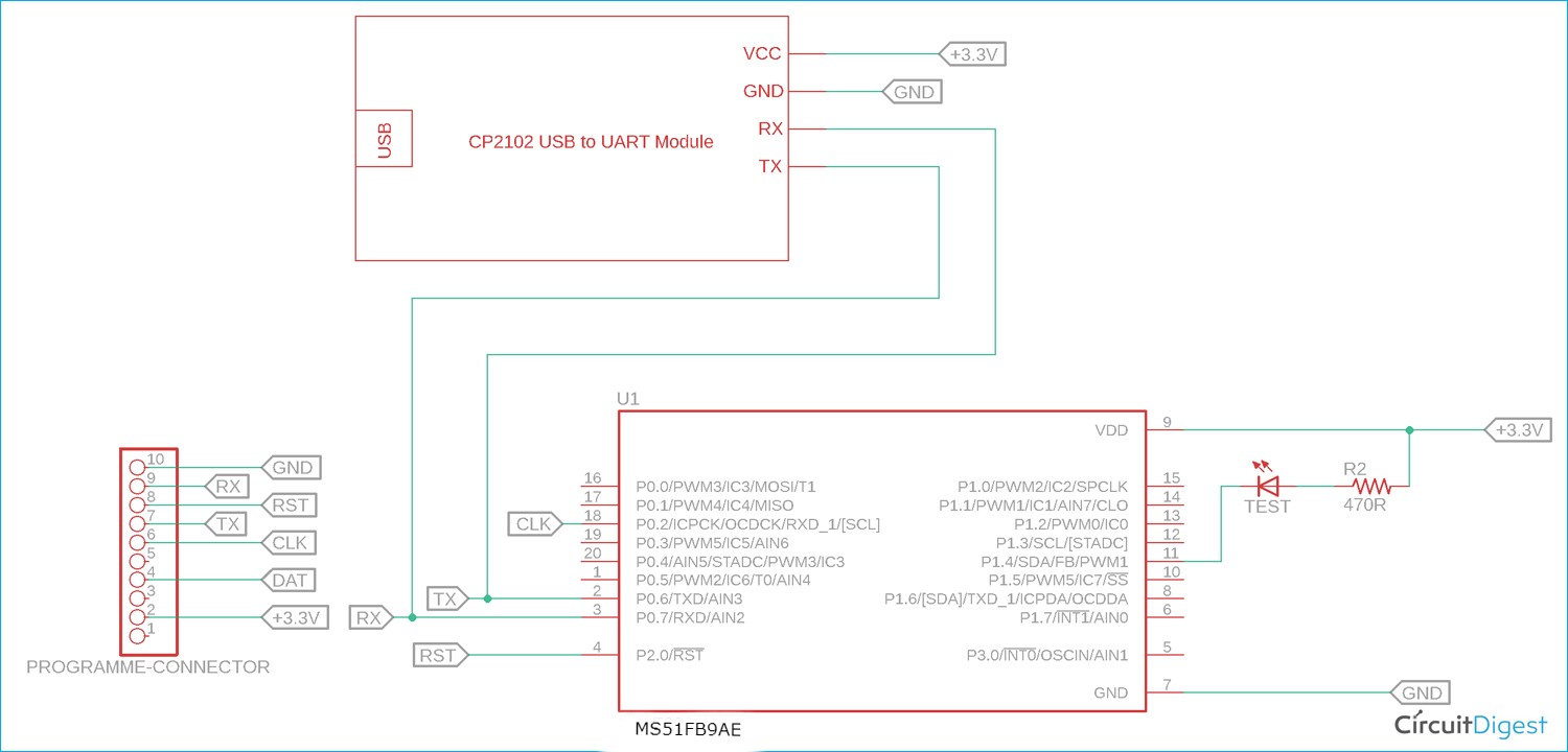
You can also take reference from the circuit diagram given below to interface your GSM module with a microprocessor:-
In this article, we learned about the GSM modules, their functionalities, and how they can be interface with various devices and technologies.
For more helpful and interesting articles related to interfacing and modules, feel free to check out our other blogs by clicking here.

