Over-The-Air (OTA) firmware updates are a crucial aspect of embedded systems, allowing developers to remotely update software on devices without physical access. One of the best things about ESP32 is that its firmware can be updated wirelessly. This kind of programming is called “Over-The-Air” (OTA). In this blog post, we will explore the process of performing OTA firmware updates over ESP32, ESP32 is a popular microcontroller-based development board with built-in Wi-Fi and Bluetooth capabilities.
Follow this step-by-step guide to ensure a seamless and efficient OTA update process for your ESP32-based devices.
What is OTA Programming in ESP32?
OTA programming allows for updating/uploading new programs to the ESP-WROOM-32 over Wi-Fi without the need for a USB connection to a computer.
It provides a wireless method to perform program updates on the ESP32 module.
Benefits of OTA Programming
Convenience: OTA programming proves advantageous when physical access to the ESP module is not feasible or practical.
Time-saving: It reduces the time required to update each ESP module during maintenance, as updates can be performed remotely.
Advantages of OTA Programming
Centralized Updates: OTA programming enables a single central location to send updates to multiple ESP32 modules connected to the same network.
Scalability: The ability to update multiple ESPs simultaneously streamlines the update process for large-scale deployments.
*The only requirement is to include OTA code in every code you want to do OTA to enable OTA functionality for more future updates.
There are 3 Simple Steps for Implementing Basic OTA with the ESP32
1. Writing Main Code with Basic OTA Function
In the first step we will write a main code with a function of Basic OTA.
*Refer the below code:
#include <WiFi.h>
#include <ESPmDNS.h>
#include <WiFiUdp.h>
#include <ArduinoOTA.h>
const char* ssid = "..........";
const char* password = "..........";
void setup() {
Serial.begin(115200);
Serial.println("Booting");
WiFi.mode(WIFI_STA);
WiFi.begin(ssid, password); // change to your SSID and Password
while (WiFi.waitForConnectResult() != WL_CONNECTED) {
Serial.println("Connection Failed! Rebooting...");
delay(5000);
ESP.restart();
}
// Port defaults to 3232
// ArduinoOTA.setPort(3232);
// Hostname defaults to esp3232-[MAC]
// ArduinoOTA.setHostname("myesp32");
// No authentication by default
// ArduinoOTA.setPassword("admin");
// Password can be set with it's md5 value as well
// MD5(admin) = 21232f297a57a5a743894a0e4a801fc3
// ArduinoOTA.setPasswordHash("21232f297a57a5a743894a0e4a801fc3");
ArduinoOTA
.onStart([]() {
String type;
if (ArduinoOTA.getCommand() == U_FLASH)
type = "sketch";
else // U_SPIFFS
type = "filesystem";
// NOTE: if updating SPIFFS this would be the place to unmount SPIFFS using SPIFFS.end()
Serial.println("Start updating " + type);
})
.onEnd([]() {
Serial.println("\nEnd");
})
.onProgress([](unsigned int progress, unsigned int total) {
Serial.printf("Progress: %u%%\r", (progress / (total / 100)));
})
.onError([](ota_error_t error) {
Serial.printf("Error[%u]: ", error);
if (error == OTA_AUTH_ERROR) Serial.println("Auth Failed");
else if (error == OTA_BEGIN_ERROR) Serial.println("Begin Failed");
else if (error == OTA_CONNECT_ERROR) Serial.println("Connect Failed");
else if (error == OTA_RECEIVE_ERROR) Serial.println("Receive Failed");
else if (error == OTA_END_ERROR) Serial.println("End Failed");
});
ArduinoOTA.begin();
Serial.println("Ready");
Serial.print("IP address: ");
Serial.println(WiFi.localIP());
}
void loop() {
ArduinoOTA.handle(
Due to the absence of OTA upgrade capability in the ESP32's factory image, it is necessary to initially load the OTA firmware onto the ESP32 using a serial interface. That’s why It is required to first upload the firmware serially in order to perform subsequent updates over-the-air.
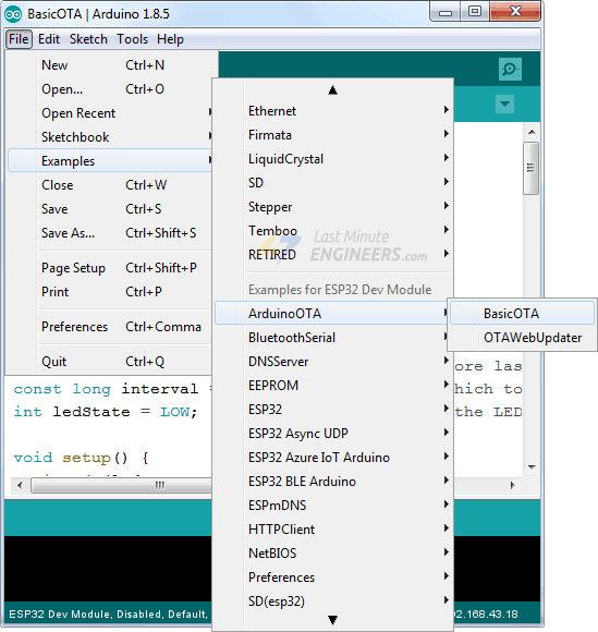
The ESP32 add-on for the Arduino IDE includes an OTA library as well as a BasicOTA example. Simply navigate to File > Examples > ArduinoOTA > BasicOTA.
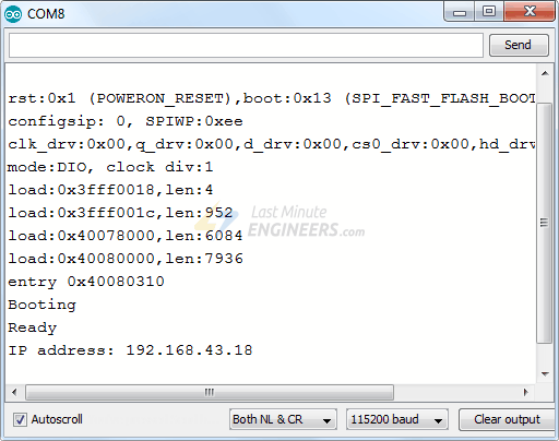
Next, launch the Serial Monitor with a baud rate of 115200 and press the EN button on the ESP32. Assuming everything is functioning properly, you will observe the dynamic IP address assigned by your router. Take note of this IP address for future reference.
3. Uploading New Sketch Over-the-Air i.e OTA
Now, it's time to perform an over-the-air upload of a new sketch.
Keep in mind that including the OTA code in each sketch is crucial. Failure to do so will result in the loss of OTA capability, preventing you from performing future over-the-air uploads.
To ensure OTA functionality, it is advised to modify the previous code to incorporate your new code. As an illustration, we will integrate a basic Blink sketch into the existing Basic OTA code.
*Refer Below Code:
#include <WiFi.h>
#include <ESPmDNS.h>
#include <WiFiUdp.h>
#include <ArduinoOTA.h>
const char* ssid = "..........";
const char* password = "..........";
//variabls for blinking an LED with Millis
const int led = 2; // ESP32 Pin to which onboard LED is connected
unsigned long previousMillis = 0; // will store last time LED was updated
const long interval = 1000; // interval at which to blink (milliseconds)
int ledState = LOW; // ledState used to set the LED
void setup() {
pinMode(led, OUTPUT);
Serial.begin(115200);
Serial.println("Booting");
WiFi.mode(WIFI_STA);
WiFi.begin(ssid, password);
while (WiFi.waitForConnectResult() != WL_CONNECTED) {
Serial.println("Connection Failed! Rebooting...");
delay(5000);
ESP.restart();
}
// Port defaults to 3232
// ArduinoOTA.setPort(3232);
// Hostname defaults to esp3232-[MAC]
// ArduinoOTA.setHostname("myesp32");
// No authentication by default
// ArduinoOTA.setPassword("admin");
// Password can be set with it's md5 value as well
// MD5(admin) = 21232f297a57a5a743894a0e4a801fc3
// ArduinoOTA.setPasswordHash("21232f297a57a5a743894a0e4a801fc3");
ArduinoOTA
.onStart([]() {
String type;
if (ArduinoOTA.getCommand() == U_FLASH)
type = "sketch";
else // U_SPIFFS
type = "filesystem";
// NOTE: if updating SPIFFS this would be the place to unmount SPIFFS using SPIFFS.end()
Serial.println("Start updating " + type);
})
.onEnd([]() {
Serial.println("\nEnd");
})
.onProgress([](unsigned int progress, unsigned int total) {
Serial.printf("Progress: %u%%\r", (progress / (total / 100)));
})
.onError([](ota_error_t error) {
Serial.printf("Error[%u]: ", error);
if (error == OTA_AUTH_ERROR) Serial.println("Auth Failed");
else if (error == OTA_BEGIN_ERROR) Serial.println("Begin Failed");
else if (error == OTA_CONNECT_ERROR) Serial.println("Connect Failed");
else if (error == OTA_RECEIVE_ERROR) Serial.println("Receive Failed");
else if (error == OTA_END_ERROR) Serial.println("End Failed");
});
ArduinoOTA.begin();
Serial.println("Ready");
Serial.print("IP address: ");
Serial.println(WiFi.localIP());
}
void loop() {
ArduinoOTA.handle();
//loop to blink without delay
unsigned long currentMillis = millis();
if (currentMillis - previousMillis >= interval) {
// save the last time you blinked the LED
previousMillis = currentMillis;
// if the LED is off turn it on and vice-versa:
ledState = not(ledState);
// set the LED with the ledState of the variable:
digitalWrite(led, ledState);
}
}
* It's important to note that the delay() function has not been utilized to control the LED blinking. This can result in missed OTA requests, potentially causing interruptions in the program execution.
After copying the above sketch to your Arduino IDE, navigate to Tools > Port option. Look for: esp32-xxxxxx at your_esp_ip_address. If you are unable to locate it, just restart your IDE.

Select the appropriate port and click on the Upload button. The new sketch will be swiftly uploaded within a few seconds. As a result, the on-board LED will initiate its blinking pattern.
Applications of Firmware OTA using ESP32
Firmware OTA is the most required application for the deployed IoT devices. The requirement of devices having OTA enabled is increasing day-by-day.
There are several applications where the OTA is in much need such as:
Industrial Automation
Home Automation
Wearable Devices
Remote Sensing and Monitoring
Conclusion
OTA updates not only save time and resources but also provide a path to enhance features, fix bugs, and improve security without physical access to the devices. So, embrace the power of OTA updates and keep your ESP32-based devices up to date effortlessly!
If you are looking for ESP32, WiFi or Bluetooth modules, or different microcontrollers from brands such as Espressif and Ai-Thinker to implement above project or you are looking for microcontrollers and different sensors or any project guidance reach out to us at Campus Component today!

