What is a Contactor?
A contactor is a switch in an electrical power circuit, similar to relays, which is designed to handle high currents. They are very important in electrical systems, and they are safe & efficient in switching high-power devices. They are mostly used for controlling electric motors, lighting systems, heating equipment, and other heavy-duty electrical devices.
Contactors are controlled by an electromagnetic coil when they are energized, closing the circuit and allowing current to flow to the connected load. Contactors are used as an important part of motor starters, HVAC systems, lighting controls, and various automated electrical networks.
Contactor Symbol, and Representation
Contactor symbol is made of a rectangle with coil designation (e.g., “K”) and associated contact symbols.

The contactor coil is usually represented by a rectangle with terminal numbers (e.g., A1 and A2) indicating coil connections.
Contact Representation - Contacts are shown separately from the coil using lines and symbols normally open (NO) contacts are shown as two parallel lines, and normally closed (NC) contacts as one straight and one angled line.
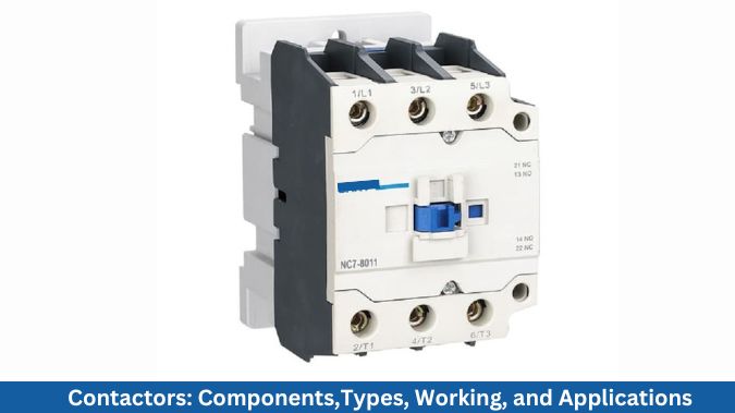
Components of Contactors
Components of contactors ensure the safe and efficient operation under high electrical loads.
1. Electromagnetic Coil
This is the main component in the contactor, which is responsible for generating the magnetic field required to operate the switch. When voltage is applied to the coil terminals A1 & A2, it generates a magnetic force that pulls in the armature, closes the main contact,s and completes the circuit.
2. Armature
Armature is a movable iron core that gets attracted to the coil’s magnetic field. It is made up of silver alloy. The movement of the armature causes the main contacts, and these contacts are typically designed to handle high current loads.
3. Auxiliary Contacts
These contacts are used for signaling, interlocking, or control functions. They can be normally open (NO) or normally closed (NC) and are often used in control circuits.
4. Enclosure and Arc Chutes
Enclosure provides insulation and mechanical protection, and arch chutes help to extinguish electrical arcs which formed when the contacts open under load.
Types of Contactors
Based on the design, operating mechanism, and application, contactors are classified as electromagnetic, manual, magnetic, AC, and DC contactors.
1. Electromagnetic Contactors
Electromagnetic contactors operate using an electromagnetic coil which, when energized, pulls the movable armature into close the contacts and allows the current to flow through the circuit. They are used for remote and automatic switching of high-power loads, such as motors and heavy machinery.
Manual Contactors
Manual contactors require human intervention to operate. The push button is required in these types of devices to open or close the circuit. Mostly manual contactors are used in remote operation, and they are valued for their straightforward operation.
Magnetic Contactors
They use a magnetic field to operate the switching mechanism. They are mainly used for frequent switching mechanisms and are widely used in motor control centres, HVAC systems, and industrial automation. They offer various features like overload protection, arc suppression, and durability, which makes them suitable for continuous duty applications.
AC Contactors
They are designed for controlling alternating current circuits. AC contactors have components that are optimized for the nature of AC power, such as arc chutes and laminated cores to reduce humming and heat. They are commonly used in lighting, heating, and motor control applications.
DC Contactors
DC contactors are used to switch direct current circuits. They are used to handle the constant voltage and higher arc energy associated with DC power. These contactors include specialized arc suppression techniques and are often used in battery-powered systems, electric vehicles, and solar applications.
Functions of Contactors
Contactors are used to turn high-power electrical devices ON and OFF remotely or automatically.
For managing the function like starting, stopping, and reversing, contactors are used in motor starters.
Contactors isolate the control circuit from the high-voltage power circuit, which ensures user and system safety.
Contactors enable the remote control from a distance using control signals, ideal for automation.
Contactors are often integrated with overload relays to disconnect power during fault or overload conditions.
Contactors are used in large commercial setups to manage lighting circuits and heating elements efficiently.
Contactors Working Principles
Contactors' working principle is based on electromagnetic switching, which allows for to control high-power electrical circuits using a low-voltage control signal.
When an electrical current flows through the contactor’s coil, it generates a magnetic field that pulls a movable iron armature toward the coil.
This movement causes the main contacts to close, completing the circuit and allowing current to flow to the connected electrical load, such as a motor or lighting system.
When the coil is de-energized, the magnetic field collapses, and a spring mechanism pushes the armature back to its original position. This action opens the contacts and interrupts the current flow, effectively turning off the load.
Contactors usually feature normally open (NO) main contacts, which means the circuit remains open until the coil is energized.
To enhance safety and performance, contactors may also include arc suppression mechanisms, such as arc chutes, to safely extinguish electrical arcs formed when contacts open under load. Additionally, auxiliary contacts are often integrated for signaling or interlocking purposes in control systems.
Contactor Wiring Diagram
A contactor wiring diagram is a schematic representation showing how a contactor is connected within an electrical circuit to control a load such as a motor or lighting system.
It includes components like contactor coil (A1 and A2 terminals), main contacts (L1, L2, L3 to T1, T2, T3), overload relay, auxiliary contacts, and power source.
Wiring diagrams typically separate the power circuit (handling high current to the load) from the control circuit (managing the contactor's coil).
The coil is connected to a control switch or push button, often in series with protection devices like fuses or circuit breakers.
A basic contactor diagram includes a start button (NO) and a stop button (NC) connected in series to control the coil energization.
An overload relay is usually wired in series with the contactor to protect motors from overheating and current surges.
Auxiliary contacts are shown in the diagram to provide latching or interlocking functions, enhancing control and automation.
For motor control, the diagram shows three-phase input (L1, L2, L3) connected to the contactor’s top terminals, and output to the motor from T1, T2, T3.
Proper neutral (N) and ground (PE) connections are indicated for safe and reliable operation.

Difference Between Contactors and Relays
Contactors | Relays |
Contactors are designed to handle high current loads (typically above 10A). | Relays are used for low current applications (usually below 10A). |
Contactors are used in industrial and power systems to control electric motors, lighting, and heavy machinery. | Relays are commonly used in control circuits, signaling, and low-power automation systems. |
Contactors are larger and more robust to manage high-power switching. | Relays are smaller and lighter, suitable for compact circuits. |
Contactors include arc chutes or suppression features to handle electric arcs from high voltage switching. | Relays generally do not need arc suppression due to low voltage use. |
Contactors are built for frequent and long-duration switching operations. | Relays are ideal for occasional switching and signal transmission. |
Contactors often come with multiple auxiliary contacts for advanced control. | Relays may have fewer or simpler auxiliary contact configurations. |
Contactors are more durable and suited for inductive loads like motors. | Relays are mainly used for resistive loads such as lights and fans. |
Contactors are more expensive due to their size and capability. | Relays are generally less expensive and simpler in design. |
Applications of Contactors
Contactors are used extensively to start, stop, and reverse electric motors in industrial machinery and automation systems.
They are employed to control large lighting circuits in commercial buildings, stadiums, and street lighting systems.
Integral in heating, ventilation, and air conditioning systems for switching compressors, fans, and pumps.
Contactors are used to manage the distribution and switching of power in electrical panels and substations.
Essential in automated production lines, PLC systems, and control panels for remote and sequenced operations.
Contactors are applied in power factor correction units to switch capacitor banks on and off automatically.
Contactors are utilized to control water pumps, irrigation systems, and sewage treatment equipment.
Frequently Asked Questions
1.What is the most common reason for contactor failure?
The most common reason for contactor failure is contact wear due to frequent switching and electrical arcing.
2. What happens when a contactor fails?
When a contactor fails, it can result in equipment not starting, stopping unexpectedly, or continuous operation due to stuck or burned contacts.
3. What is the function of AC contactor?
The function of an AC contactor is to switch and control the flow of AC electrical power to loads such as motors, lighting, and heating systems.
4.Are contactors AC or DC?
Contactors are available in both AC and DC versions, depending on the application and coil voltage requirements.
5. Does a contactor reduce voltage?
No, a contactor does not reduce voltage; it simply switches electrical power on or off in a circuit.
6. How do you test if a contactor is bad?
You can test if a contactor is bad by checking coil voltage and measuring continuity across the contacts using a multimeter.
7. Can a contactor work without a coil?
No, a contactor cannot work without a coil, as the coil is essential for creating the magnetic field that closes the contacts.

