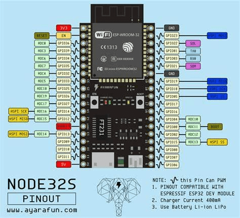
ESP – 32 is a low cost, low power microcontroller. It has integrated Wi-Fi, and Bluetooth. It employs Tensilica Xtensa LX – 6 microprocessor, Xtensa LX – 5 microprocessor or RISC – V microprocessor. It has built – in antenna, switches, power amplifier, filters and power modules.
Features:
CPU: Xtensa single core 32 bit LX6 microprocessor.
Operating: 160 MHZ
Memory: 32 KB
Connectivity:
Wi – Fi: 802.11 b/g/n
Bluetooth: v4.2 BR/EDR and BLE (shares the radio with Wi-Fi)
Peripheral Interface:
34 × programmable GPIOs
12-bit SAR ADC up to 18 channel
2 × 8-bit DACs
10 × touch sensors ( capacitive sensing GPIOs)
4 × SPI
2 × I2S interfaces
2 × I2C interfaces
3 × UART
SD/SDIO /CE - ATA /MMC /eMMC host controller
SDIO/SPI slave controller
Ethernet MAC interface with dedicated DMA and planned IEEE 1588 Precision Time Protocol support
CAN bus 2.0
Infrared remote controller (TX/RX, up to 8 channels)
Pulse counter (capable of full quadrature decoding)
Motor PWM
LED PWM (up to 16 channels)
Hall effect sensor
Ultra low power analog pre-amplifier
Security:
IEEE 802.11 standard security features all supported, including WPA, WPA2, WPA3 (depending on version) and WLAN Authentication and Privacy Infrastructure (WAPI)
Secure boot
Flash encryption
1024-bit OTP, up to 768-bit for customers
Cryptographic hardware acceleration: AES, SHA - 2, RSA, Ellipric Curve Cryptography (ECC),Random Number Generator (RNG)
Power management:
Internal low dropout generator
Individual power domain for RTC
μA deep sleep current
Wake up from GPIO interrupt, timer, ADC measurements, capacitive touch sensor interrupt
Interfacing an LED:
Connect the positive end of the LED to 100 Ohm resistor. Connect another end of the resistor to pin 18. Connect the negative end to GND.
Code:
/*ESP32 LED BLINK
*/
#define 18
Void setup() {
//set pin
Pinmode (18,OUTPUT);
}
void loop {
delay (500);
digitalWrite(18,HIGH); //LED TURN ON
delay(500);
digitalWrite(18,LOW); //LED TRM OFF
}
Interfacing a switch:
Components:
1 push button switch
1 LED
2 Resistors 100 ohm
Jumper wires
Bread board
Circuit:
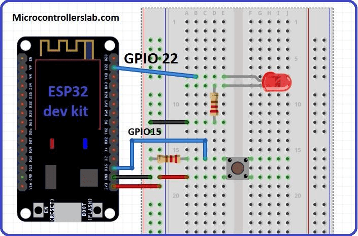
Check the switch connectivity with a multimeter. Place the switch on the breadboard (please refer to the image). Connect one pin to Pin 15 of ESP 32. Connect a resistor in series with Pin 18 and GND. Connect another pin to 5V of ESP 32. On the other side, Place a LED on the breadboard. Connect a resistor in series with Pin 19 and positive terminal of LED. Ground the negative terminal.
Working:
When we press the switch the circuit gets completed pin 15 gets 5V. This is a pull up mode. When the resistor is connected between +Vcc and switch it is in pull up mode. When the resistor is connected between switch and GND it is pill down mode. We can use any of the two.
As pin 15 gets a signal we turn Pin 22 high. Thus the LED glows.
Code:
#define 15
#define 22
void setup() {
//declare pin 15 as input
pinMode(15, INPUT);
//declare pin 22 as output
pinMode(22,OUTPUT);
}
void loop() {
//checkes the pin is high or low, condition statement
//if switch is ressed LED will turn on else will remain off
if (15==HIGH)
{
digitalWrite(22,HIGH);
}
else
{
digitalWrite(22,LOW);
}
}
Thus we have seen how to interface a LED and a switch with ESP 32. After going through this you would surely be able to use the GPIO pins.

